UART
UART Overview
UART Overview - VAR-SOM-MX93
The VAR-SOM-MX93 and DART-MX93 expose up to seven LPUART interfaces, some of which are multiplexed with other peripherals.
| Serial Port | Device Node | Device Tree | VAR-SOM-MX93 / Symphony Board | DART-MX93 / DT8MCustomBoard | Sonata V1.1 connector |
|---|---|---|---|---|---|
| UART0 | /dev/ttyLP0 | lpuart1 | Symphony board serial console | DT8MCustomboard serial console | — |
| UART2 | /dev/ttyLP2 | lpuart3 | Disabled by default, see datasheet | Disabled by default, see datasheet | — |
| UART3 | /dev/ttyLP3 | lpuart4 | Disabled by default, see datasheet | Disabled by default, see datasheet | — |
| UART4 | /dev/ttyLP4 | lpuart5 | 1.8V Signal level, used on SOM for Bluetooth interface and is accessible only when Bluetooth is disabled. [1] | 1.8V Signal level, used on SOM for Bluetooth interface and is accessible only when Bluetooth is disabled. [1] | — |
| UART5 | /dev/ttyLP5 | lpuart6 | Connected to Symphony board J18.7 and J18.9 | Connected to DT8MCustomboard J12.4 and J12.6 | J6.4 / J6.6 |
| UART6 | /dev/ttyLP6 | lpuart7 | Connected to Symphony board J18.3 and J18.5 | Connected to DT8MCustomboard J12.11 and J12.13 | J6.11 / J6.13 |
| UART7 | /dev/ttyLP7 | lpuart8 | Disabled by default, see datasheet | Disabled by default, see datasheet | — |
A dash in the Sonata column means this table does not specify a corresponding connection.
Disabling Bluetooth / Enabling UART4 (/dev/ttyLP4)
UART4/ttyLP4 is used by the Bluetooth on the SOM. To use it on the carrier board, Bluetooth must be disabled on the SOM.
First, disable variscite-bt by running:
systemctl stop variscite-bt; systemctl stop variscite-ot
systemctl disable variscite-bt; systemctl disable variscite-ot
Then, disable Bluetooth in the device tree imx93-var-som.dtsi or imx93-var-dart.dtsi:
Testing UART5
Connect the UART5 loopback pins for your carrier, then run the commands below:
| Signal | DT8MCustomBoard | Sonata-Board |
|---|---|---|
| Loopback | J12.4 / J12.6 | J6.4 / J6.6 |
For each invocation of the echo command the "hello" string should appear on the terminal.
Testing UART6
Connect the UART6 loopback pins for your carrier, then run the commands below:
| Signal | DT8MCustomBoard | Sonata-Board |
|---|---|---|
| Loopback | J12.11 / J12.13 | J6.11 / J6.13 |
For each invocation of the echo command the "hello" string should appear on the terminal.
Disabling UART6
To disable UART6 edit arch/arm64/boot/dts/freescale/imx93-var-dart-dt8mcustomboard.dts or arch/arm64/boot/dts/freescale/imx93-var-dart-dt8mcustomboard.dts in the kernel source directory and modify
to
Other UARTs can be disabled in a similar manner by referencing the table above.
Configuring RS485 Half-Duplex
The i.MX93 supports controlling an rs485 transceiver driver enable using RTS_B. For more details, please refer to 63.3.4.4 Transceiver driver enable using RTS_B of the i.MX 93 Applications Processor Reference Manual.
RS485 is enabled in software by:
- Enabling the RTS pin in the device tree.
- Enabling RS485 in the serial driver.
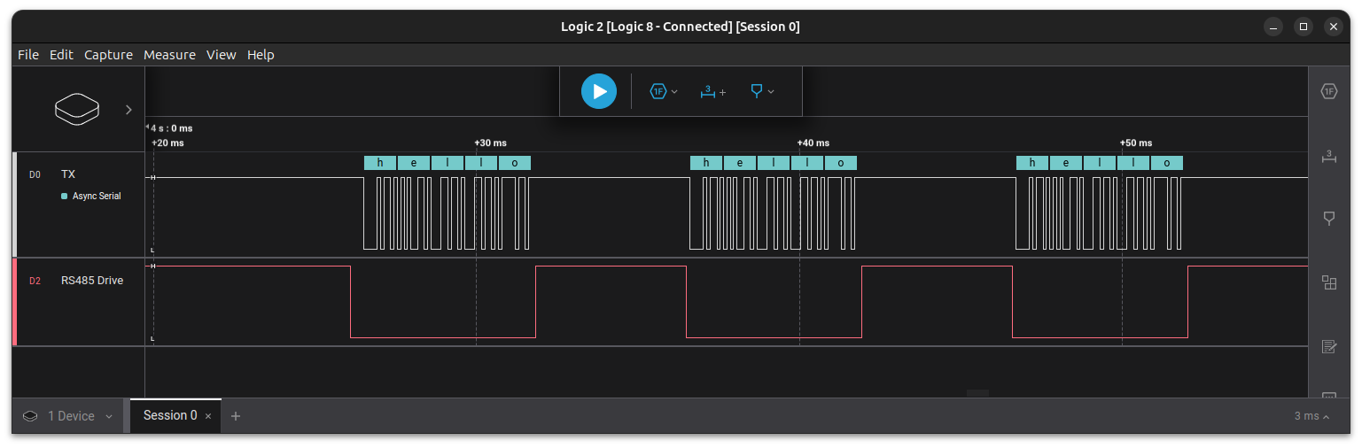
The example below demonstrates how to do this on the VAR-SOM-MX93 using /dev/ttyLP6 on J18.3 (TX), J18.4 (RX) and J17.8 (RTS).
First, disable the ov5640_mipi0 which uses the RTS pin:
Then, configure the RTS pinmux in pinctrl_uart7:
After booting the updated device tree, use the following python script to test RS485:
import sys
import serial
import serial.rs485
import time

def configure_rs485(port, data):
    try:
        # Open the serial port
        ser = serial.Serial(port, baudrate=9600)

        # Configure RS485
        ser.rs485_mode = serial.rs485.RS485Settings(
            delay_before_tx=0,
            delay_before_rx=0,
            rts_level_for_tx=False,  # RTS is low during transmission
            rts_level_for_rx=True,   # RTS is high during reception
            loopback=False
        )

        # Write data to the port three times with a delay of 10ms between each
        for _ in range(3):
            ser.write(data.encode())
            time.sleep(0.01)  # 10ms delay

        # Close the serial port
        ser.close()

        print("Data sent successfully.")

    except Exception as e:
        print(f"Error: {str(e)}")

if __name__ == "__main__":
    if len(sys.argv) != 3:
        print("Usage: python3 rs485.py <port> <data>")
    else:
        port = sys.argv[1]
        data = sys.argv[2]
        configure_rs485(port, data)
Finally, install pyserial and run the script:
The following image was captured on a logic analyzer using this example: