GPIO
GPIO state
Note: The GPIO assignments displayed below are for reference purposes and may differ slightly depending on the release, the state of the system and the carrier board revision.
The current state of the system's GPIOs can be obtained in user-mode, as shown in the following example:
Warning If the output state of a GPIO is correct depends on the Device Tree
setting. The value can only be read back properly if the pad is configured with
PIN_INPUT. See
Define a Pin as GPIO in the Device Tree
for details
# cat /sys/kernel/debug/gpio
gpiochip0: GPIOs 512-603, parent: platform/600000.gpio, 600000.gpio:
 gpio-522 (                    |powerdown           ) out hi
 gpio-533 (                    |ov5640-buf-en       ) out lo ACTIVE LOW
 gpio-534 (                    |reset               ) out hi ACTIVE LOW
 gpio-542 (                    |regulator-1         ) out hi
 gpio-558 (                    |int-eth-phy-vdd     ) out hi
 gpio-560 (                    |pendown             ) in  hi ACTIVE LOW
 gpio-561 (                    |reset               ) out hi ACTIVE LOW
 gpio-565 (                    |regulator-2         ) out hi
 gpio-566 (                    |reset               ) out lo ACTIVE LOW
 gpio-568 (                    |vdd_sd_vio          ) out lo
 gpio-571 (                    |reset               ) out lo ACTIVE LOW

gpiochip1: GPIOs 604-655, parent: platform/601000.gpio, 601000.gpio:
 gpio-616 (                    |id                  ) in  lo
 gpio-617 (                    |spi5 CS0            ) out lo ACTIVE LOW

gpiochip2: GPIOs 656-663, parent: i2c/0-0020, 0-0020, can sleep:
 gpio-656 (                    |Heartbeat           ) out hi ACTIVE LOW
 gpio-657 (                    |Back                ) in  hi IRQ ACTIVE LOW
 gpio-658 (                    |Home                ) in  hi IRQ ACTIVE LOW
 gpio-659 (                    |Menu                ) in  hi IRQ ACTIVE LOW
 gpio-660 (                    |usb3_sel            ) out lo
 gpio-661 (                    |PHY reset           ) out hi ACTIVE LOW
 gpio-662 (                    |eth-vselect         ) out lo
 gpio-663 (                    |eth-mdio-enable     ) out hi
Each GPIO is defined as in or out and the state is shown as lo or hi. For example pin 657 is the Back button. When the Back button is not pressed, the state will be:
When the Back button is pressed, the state will be:
Manipulating GPIO using libgpiod
libgpiod provides bindings and utilities for manipulating GPIO via user-space.
libgpiod via command-line
libgpiod provides command-line utilities for GPIO:
| gpiodetect | List all gpiochips present on the system, their names, labels and number of GPIO lines |
| gpioinfo | List all lines of specified gpiochips, their names, consumers, direction, active state and additional flags |
| gpioget | Read values of specified GPIO lines |
| gpioset | Set values of specified GPIO lines, potentially keep the lines exported and wait until timeout, user input or signal |
| gpiofind | Find the gpiochip name and line offset given the line name |
| gpiomon | Wait for events on GPIO lines, specify which events to watch, how many events to process before exiting or if the events should be reported to the console |
The AM62P GPIOs exist in two domains, the MAIN domain and the MCU domain.
The MAIN domain includes two General Purpose Input/Output (GPIO) modules that provide dedicated general-purpose pins that can be configured as either inputs or outputs. The GPIO modules main features include:
- Support of 9 banks x 16 GPIO pins
- Support of up to 9 banks of interrupt capable GPIOs
- Interrupts can be triggered by rising and/or falling edge, specified for each interrupt capable GPIO pin
- Set/clear functionality per individual GPIO pin
The MCU domain includes one General Purpose Input/Output (MCU_GPIO) module provides dedicated general-purpose pins that can be configured as either inputs or outputs. the MCU_GPIO module includes these main features:
- Support of 9 banks x 16 GPIO pins
- Support of up to 9 banks of interrupt capable GPIOs
- Interrupts can be triggered by rising and/or falling edge, specified for each interrupt capable GPIO pin
- Set/clear functionality per individual GPIO pin
Each module corresponds to a character device /dev/gpiochip<bank index>.
Depending on the carrier boad revision there might also be one or two GPIO Expander which also correspond to a character device.
The gpiodetect utility can be used to inspect the available gpiochip character
devices:
# gpiodetect
gpiochip0 [600000.gpio] (92 lines)
gpiochip1 [601000.gpio] (52 lines)
gpiochip2 [0-0020] (8 lines)
These can be mapped to the device tree:
| gpiochip | devicetree | address |
|---|---|---|
| gpiochip0 | main_gpio0 | 0x600000 |
| gpiochip1 | main_gpio1 | 0x601000 |
| gpiochip2 | pca9534 | i2c0@20 |
The gpioinfo utility can be used to inspect the lines for a given gpiochip:
gpioinfo -c2
gpiochip2 - 8 lines:
        line   0:       unnamed                 output active-low consumer=Heartbeat
        line   1:       unnamed                 input active-low consumer=Back
        line   2:       unnamed                 input active-low consumer=Home
        line   3:       unnamed                 input active-low consumer=Menu
        line   4:       unnamed                 output consumer=usb3_sel
        line   5:       unnamed                 output active-low consumer=PHY reset
        line   6:       unnamed                 output consumer=eth-vselect
        line   7:       unnamed                 output consumer=eth-mdio-enable
The gpioset and gpioget utilities can be used to manipulate GPIO from the
command-line.
For example, assuming GPIO1_4 (gpiochip1 and main_gpio1 in the device tree) is configured as a GPIO in your device tree:
Set GPIO1_4 high:
Set GPIO1_4 low:
Read GPIO1_4:
libgpiod C Application
libgpiod provides bindings for C/C++ applications. C++ examples are available in the libgpiod /tree/bindings/cxx/examples directory.
Below is a simple C application demonstrating how to use the bindings with GPIO1_4:
Makefile:
main.c
#include <gpiod.h>
#include <stdio.h>
#include <unistd.h>
#include <stdlib.h>
#include <string.h>

#define    CONSUMER    "Variscite Demo"

int main(int argc, char **argv)
{
    unsigned int i, ret, val;
    struct gpiod_chip *chip;
    struct gpiod_line *line;
    const char * chipname = "gpiochip1";        /* adjust gpiochip according to your system */
    const unsigned int line_num = 4;

    chip = gpiod_chip_open_by_name(chipname);
    if (!chip) {
        perror("Open chip failed\n");
        goto end;
    }

    line = gpiod_chip_get_line(chip, line_num);
    if (!line) {
        perror("Get line failed\n");
        goto close_chip;
    }

    ret = gpiod_line_request_output(line, CONSUMER, 0);
    if (ret < 0) {
        perror("Request line as output failed\n");
        goto release_line;
    }

    /* Blink 5 times */
    val = 0;
    for (i = 0; i < 5; i++) {
        ret = gpiod_line_set_value(line, val);
        if (ret < 0) {
            perror("Set line output failed\n");
            goto release_line;
        }
        printf("Output %u on line #%u\n", val, line_num);
        sleep(1);
        val = !val;
    }

release_line:
    gpiod_line_release(line);
close_chip:
    gpiod_chip_close(chip);
end:
    return 0;
}
libgpiod Python Application
libgpiod provides bindings for python applications:
Python examples are available in the libgpiod /tree/bindings/python/examples directory.
Kernel Device Tree GPIO configuration
SysConfig Device Tree Generation
TI's SysConfig provides an intuitive graphical user interface for configuring pins, including pin mux and pad settings: https://www.ti.com/tool/SYSCONFIG.
As shown in the image below, SysConfig enables you to select the GPIO pin(s) for your design and will then generate the device tree code:
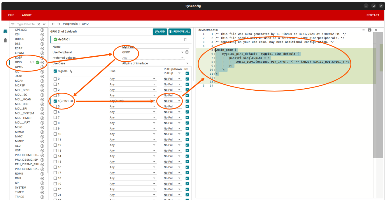
Define a pin as GPIO in the kernel Device Tree
The device tree code generated by SysConfig can be copied directly to your device tree file. Generally, GPIO will be used by another device node and you will provide it the mygpio1_pins_default handle. However, if the GPIO is not used by another device and you wish to control it using libgpiod, you need to initialize the pin configuration like shown below:
&main_pmx0 {
    pinctrl-names = "default";
    pinctrl-0 = <&mygpio1_pins_default>;
    …
    mygpio1_pins_default: mygpio1-pins-default {
        pinctrl-single,pins = <
            AM62PX_IOPAD(0x0188, PIN_INPUT, 7)    /* RGMII2_RD1.GPIO1_4 */
        >;
    };
    …
};
PIN_INPUT setting
For each pad you can configure a number of settings, including pull-up or
pull-down settings. You can also define either PIN_OUTPUT or PIN_INPUT.
The meaning of PIN_OUTPUT and PIN_INPUT are not as straight-forward as
expected:
PIN_OUTPUTmeans that this pad deactivates its input path. This means that it is not possible to read back the current value of the pad. This affects tools that are described in GPIO statePIN_INPUTactivates the input path of the pad. It is possible to read back data from that pin. That allows the usage of tools that are described in GPIO state. SettingPIN_INPUTdoes not affect the output path. A pad that is configured withPIN_INPUTcan still be driven LOW or HIGH.
Set a pad to PIN_INPUT if you care about reading back the value of the pin,
especially when you plan to use that pin as a GPIO input.
Set a pad to PIN_OUTPUT if you don't care about reading back values of the
pin. This can also reduce power consumption. Especially use PIN_OUTPUT if
the logic level to that pin is floating. Texas Instruments warns
The RXACTIVE bit must never be set without a valid logic state being sourced to the pin associated with the respective PADCONFIG register. This is very important since a floating input may damage the device.